June, '03: On the umpteenth occasion of Richard Castagnola (stoker on S/L Pegasus) telling me that I should do something about my steamboat's two pressure gauges not agreeing, I finally decided to do something. I seemed to recall an article I had heard about some years back in Model Engineer, so I took a gander at the database. After a bit of searching I unearthed the 1 October '76 edition with an article entitled: "A Pressure-Gauge Tester" by E. W. Sheppard.
The author's description, although brief, is quite clear and I set about to making my own version of the apparatus. The heart of the contraption, and the only dimensions that really matter, are those of a mating piston and cylinder, whose fit has to be within .0001 in. and as close as possible to 0.356in. dia, which nets a cross-sectional area of precisely 1/10 sq. in.. This way it's only necessary to have a 10 lb weight pressing on the weight pan's piston to get a reading of 100psi on a pressure gauge. Chasing tenths is a real exercise, but after a bit of fiddling I managed to achieve the required accuracy with my Myford lathe. Even with the required accuracy the author says up front that the tester will leak, so it's a good idea to build the tester small enough to fit within an ice tray or other small, shallow pan. I used a plastic tub, as my version was slightly larger than the author's elegant little device.
I made four different pistons before I got one I really liked. After scrapping one cylinder due to inadequate boring bar geometry I did some regrinding and had good results with my second attempt. Although the finish was adequate I wanted this one to be spot on, so I bored the thing slightly undersize and used a lap made from a bit of dowel wrapped with #600 grit sandpaper to smooth the i.d. and to bring the bore out to the final dimension.
The results of all this fiddling is an assembly that works very well. Although it does leak, it leaks less than I had feared. I've tested gauges up to 75 psi and it seems to hold this pressure without any noticeable settling of the weight tray and without me needing to top off pressure with the hand pump.
By adding trim weights and using an Ohaus Dial-a-Gram scale I brought the weight tray/piston assembly up to exactly 1/2 lb, or a reading of 5psi. To complete the kit I had to make enough weights so that I could increase this value to a gauge's normal operating pressure in predictable increments. It turns out that a two-inch diameter piece of brass or bronze weighs almost exactly one pound per inch. Additional weights for the pan were made from hunks I had on hand.
To make the weights I first chucked a short bar of brass and sanded the o.d. with some #360 grit paper and a little light oil, until the o.d. finish was mostly smooth and no longer corroded. Next I sawed the bar into rough blanks a fraction longer than an inch. I settled on a routine and made weights until I ran out of stock. Typically I first faced both ends and, using a center drill I spotted a hole maybe 1/4 in. deep in each end (so that, in case I should machine too much material off of a weight I could fill the space with a little lead). Then I'd remove the piece for a trial weighing. Using a bit of math I could calculate how much more the length had to be trimmed. As I got closer to the target value I would remove the weight, weigh it, trim a bit and repeat until I got it to within the accuracy of the scales I was using, i.e. 0.1 gram. For a one pound weight this turns out to be 1 part in 4,536, or less than 1/10 of 1 percent accuracy; plenty good enough for the task at hand.
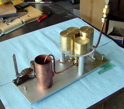
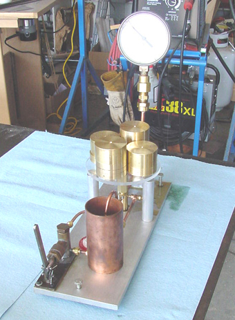
Following are photos of my completed deadweight tester.
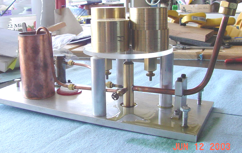
Photo #3: Close-up of business end of the device. Note that the plexiglas pan is not resting on its supports, but is floating slightly above, on the piston that is lifted by the oil under pressure in the cylinder. Note puddle of oil beneath. The valve in the foreground releases pressure at the end of the test, so that oil can return to the reservoir on the left. The red object behind the pipe, just to the right of the reservoir is a bubble level; the device must be dead level when the test occurs, so that there is no tendency of the piston to bind in the cylinder (note 3 hex bolts to achieve level). The two hexagonal brass bits beneath the weight pan are trim weights, used to get the pan to exactly 1/2 lb. The plumbing fittings are 3/16 in. MTP, as I had enough of this size to do what was needed. 1/4 in. fittings would have been better, but...