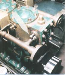
| Photo #1: Arrow points to long nut that clears obstructions on a manifold. |
|
The main problem with the Stuart 5-A is that it is a "model" (albeit a big one) of a full-size engine, meaning that clearances that would have been adequate for a hand or an arm in the larger version are too small for a finger in the chosen scale. So maintenance of things like wrist pins and packing nuts requires that the engine be removed from the boat and trundled to a workshop for disassembly. What follows is a list of steps I have had to take in order to keep the engine serviceable.
This is a model engine, no doubt about it and if I had it to do over, I would NEVER put one such in a full-size boat. Admittedly I have had it up to a screeching 800rpm, where I managed to drive Pegasus, a load of wood, my stoker and myself at a speed of 7.2mph, but this had to be close to the limits for this diminutive engine.
The price for this performance is constant maintenance and in an effort to make it easier to work on, I have made a series of small changes to its design, mainly in terms of the fasteners that secure various bits together. Model engines have "model" fasteners and they may look cute, but they are difficult to grab with "full scale" fingers. To provide decent gripping strength in a real-world situation, changes had to be made. For instance, the intake and exhaust manifolds are held on by 4-BA screws, two to a flange. Larger fasteners cannot be used because of interference where the flange collars join the manifold. The fasteners specified had to be painstakingly removed with a tiny open end wrench, because there wasn't room for a socket wrench. I drilled and tapped the casting's holes a little deeper than required on the drawing, then I made much longer than required 4-BA studs and screwed them into these holes. I fashioned some very long nuts, turned down at their base in order to clear the flange collars. The hex heads hang clear of the interference and can be gripped with a socket wrench, greatly speeding tightening and removal.
| Photo #1: Arrow points to long nut that clears obstructions on a manifold. |
|
Fasteners aside, the biggest problem on the engine involves packing the piston rod glands, which are located in a very restricted space, confined on the sides by the standards and from below by the packing nuts, which can only slide down a short distance before encountering the crankshaft. One reason that the packing gives out so regularly is that the piston rods were dreadfully cast: when turned to finished dimension, they were covered with voids and pits, which rub the heck out of the packing. Sadly, my local supplier of Stuart parts won't break out spares: it's a whole new set of castings or nothing. This quandary led me to thoughts of fabricating new piston rods from scratch, using, say, stainless steel. But the "big end" of the piston rod has some size limitations, which preclude this obvious option. After talking with others about this dilemma, Dick Vennerbeck gave me a way out: all I had to do was turn the piston rods down a hair, then sleeve them with brass tubing, the kind sold at the hobby shop. Since strength varies with the square of the cross-section, this thinning of the piston rod troubled me a bit, so I only did it to one piston rod at first, but the results are so spectacular that I have gone ahead and done the same to the other one. Now the need to replace packing has become an annual event, rather than a monthly one!
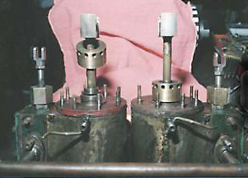
The packing nuts are designed so as to be absolutely incapable of adjustment, so I made new ones which have barring holes about their circumference. Using a special tool I can tighten the packing nuts, even when the engine is (slowly) ticking over dockside. I made three of these tools to be certain I am never without it at just the wrong moment. I keep one for a key chain, just in case!
To replace the packing, it is first necessary to break the engine apart where the cylinders rest on the standards. To do this I have to uncouple the valve rods, remove the lubricators, pull out the wrist pins and remove the 16: #2-BA nuts that hold the cylinders to the standards. After this, the whole top end can come off and be inverted on the bench. I have done this enough times that I can do it all in an afternoon, but it ain't something I would want to do without first taking the engine out of the boat. This, more than anything else, is the reason why I plan on replacing the Swan with a single-acting engine at the earliest opportunity. I will discuss this option later.
| Photo #2: Note packing nuts with barring holes. Using a special tool that is quite small, these nuts can be tightened easily, even in cramped quarters. |
|
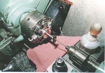
Since I am pushing the engine to its limits, lubrication is essential. In an effort to get an extra measure of oil to the mains, I have drilled 1/8" holes through the connecting rods, so that oil ports on the standards that lubricate the piston rod big ends and the wrist pins can then pass through the length of the connecting rods and drop onto the main bearings and the crankshaft, rather than be wasted. The photo below shows the split-bushing fixture that I used to grip the connecting rods in such a way that the wrist pin yokes on top and the "T"-shaped bottom ends can clear the chuck jaws. I drilled each one half-way through from one end, then reversed it in the split bushing and drilled through to connect the holes. (The red stuff is Dy-Chem: I got tired of looking at blue and bought another color!)
| Photo #3: Lathe set-up to drill through connecting rods |
|
Back in '95 I achieved a speed of 7.2mph in my 23-ft canoe, carrying myself, a stoker and a pile of wood. But in doing so I managed to stress the yokes at the top of the connecting rods into oval shapes that were about .005in. out of round. As one might expect, this caused a knocking sound so loud that it was just about impossible to talk without shouting!
The wrist pins are a mere 3/8in. in diameter and due to the slender profile of the yokes, with each "Branch" being a mere 3/16in. thick, it is impossible to drill through these slender profiles and insert a (smaller than required) tapered pin to fix the wrist pin in place without weakening the yoke over much: confining rotation to the "big end" of the piston rod would eliminate wear in the yoke's small surface area and spread it out in the piston rod "big end", whose surface area is large enough to withstand the load. If I were to stick with a double-acting steam engine, what would be needed is a much bigger wrist pin and a stouter yoke, but this would mean putting a heavier engine in my light-weight boat.
For the present, all I could do is locate the connecting rods in the mill vise, then indicate on the good end, move to the center of the yoke and bore it out round again, further weakening the slender structure in the process. After this I had my buddy Vern (who is a better welder than I am) heat up the yokes, then fill the i.d. up a bit with brazing rod, what is called "build-up rod" (and it ain't cheap: try and get one stick for a "free sample" from your welding supply shop). After this was done, I bored the yokes out again, to their proper dimension. With luck, this will see me through another season without catastrophic failure...
Since whatever repairs or refitting is required, I must whittle spares from barstock. Therefore I am sorely tempted to carve out an entire engine, a different kind of engine altogether, from scratch!
The venerable Double-acting D-valve design is compact and rugged but it uses alot of horsepower due to the number of moving parts which rub against each other. The reversing gear is a particular culprit, since it has a lot of parts that have to be dragged along for the ride, even when they are not in use. These collections of linked parts also necessitate a complicated oil distribution system to lubricate the many components that are flopping about in un-enclosed galleries. Additionally, the double-acting design means that there are separate piston rods and connecting rods, which are coupled through a wrist pin and yoke assembly that is perfect for visual enjoyment of a rotating model, but which is not very robust in actual use.
For these reasons and for a few more I am looking to acquire a more robust steam engine that I can substitute. At the moment I am enamored with poppet-valve steam engines, because of the small number of moving parts and because of my observation that the cam shaft applies a minimal load on the engine when the valves are closed. In a situation as in a small steamboat where lost fractions of a horsepower translate into a slow boat going slower still, these values become significant.
A little update: some folks have requested to see some of the renovations that are currently being undertaken on the Swan and below are some recent shots.
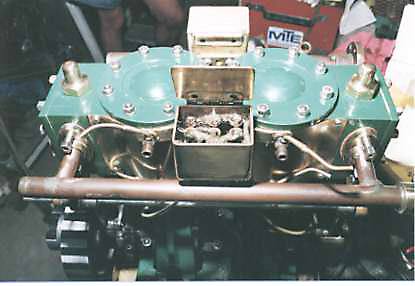
| Photo #4: Here's the top of the engine as seen from the Starboard side. In the middle you can see the dual lubricators, with the top of the starboard one open to reveal the woolen wicks which siphon lubricant to 6 key areas. The cocks to either side have lengthened handles, to make them easier to work by a person with gloves on. The intake manifold is beneath the lubricator. Eventually, the manifold will be lagged with plaster bandages from the drugstore, to insulate it. |
|
For more information on where this is leading click over to the Poppet-valve Engine project.
RETURN to S/L Pegasus