|
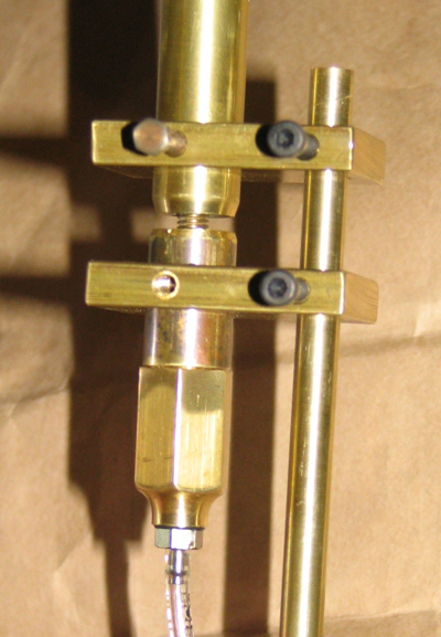
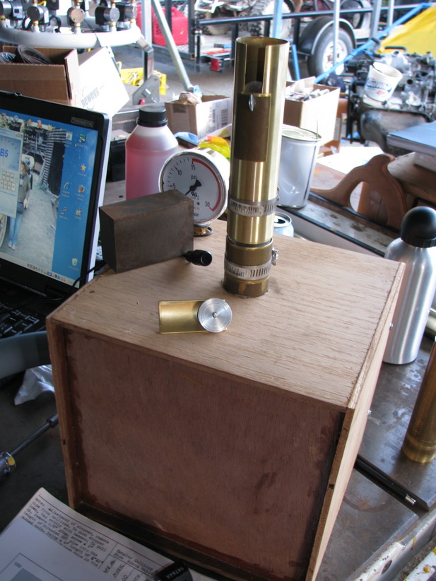
Photo #1: June/July, '07: have the basics worked out. This type of whistle is called a Helmholtz Resonator. Critical dimensions are air gap for loudness and resonator cavity length for tone. In this prototype I've made everything adjustable. There's a setscrew I can loosen to move top and bottom segments to maximize volume. I also made a sliding plug with an external indicator (note faint red arrow near bottom) to mark the cut line once various tones have been determined.
|

|
|
Photo #2: Closeup of the business end of the widget. Bottom setscrew removed for volume adjustment.
|
|
|
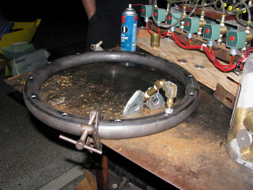
Photo #3: Jan, '09: Skipping two generations here it's early days for Calliope #4. Circular tube will become air/propane manifold and will support 12 whistles after 1/4" pipe i.d. threaded bushings are welded in place. This contraption was used to hold the bushings upright for said welding. A second pair of hands would have done a better job...
|
|
|
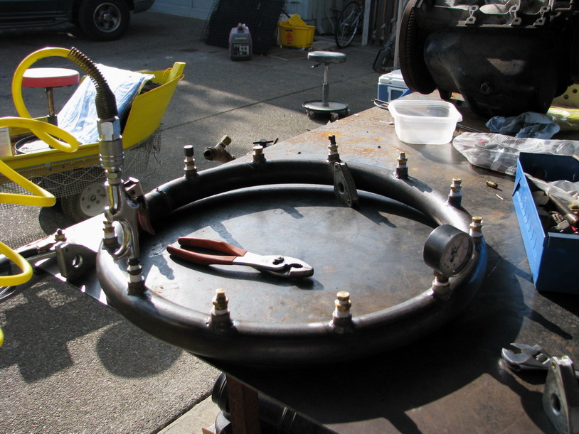
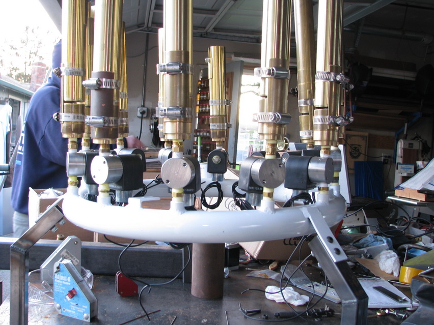
Photo #4: Manifold with welding completed and pressure test in progress.
|
|
|
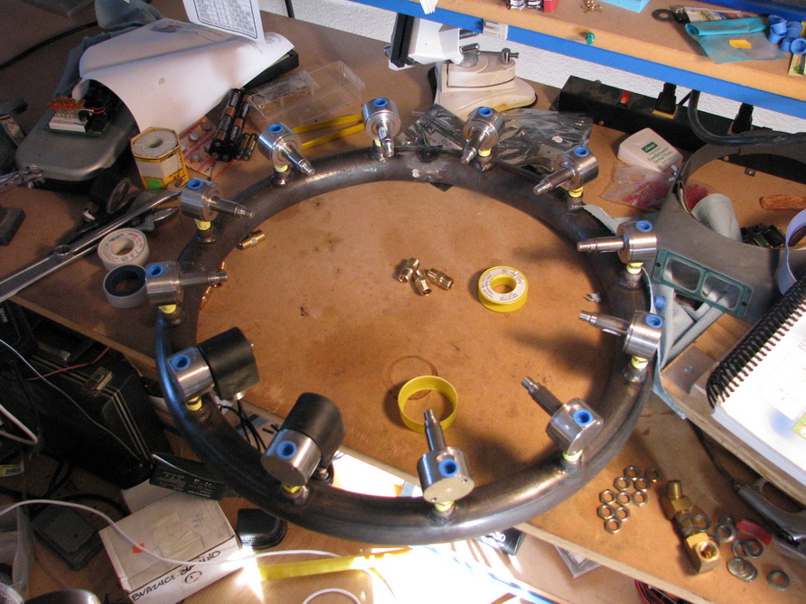
Photo #5: Valve bodies screwed in place with Propane-rated Teflon sealing tape. 220vAC solenoids removed; 24vDC solenoids have begun to replace them.
|
|
|
Photo #6: Machining air passages in bottom section of a foot. Center tapped hole is #10-32
|
|
|
Photo #7: Foot sections almost completely installed; note languids (round aluminum disks) screwed to #10-32 threaded posts.
|
|
|
Photo #8: Method of attaching Bell to Foot is just two hose clamps and a quartered section of brass pipe; simplest method is the best method.
|
|
|
Photo #9: Method adopted for tuning bells, depending on working fluid; i.e. air or propane, consists of a small section of brass pipe for a sliding 'gate', held in place with a thumbscrew threaded
into a round aluminum backing disk inside the bell.
|
|
|
Photo #10: Lathe setup for turning bells to a tunable length; i.e. parting them off to calculated lengths, plus one inch fudge factor of tuning slot. Note angle of lathe tool, to get proper bevel angle on base of bell.
|

|
|
Photo #11: Contraption for tuning whistles uses a plywood plenum with a hose from a vacuum cleaner exhaust used to 'pressurize' it. Pressure was too low to measure with the gauges I had, but the vacuum exhaust was adequate to produce a steady tone from a whistle. Using the Chromatia Tuner program, a small microphone, a graph of ideal length to frequency chart I made and a pocket calculator I could determine (approximately) how much needed to be trimmed from the bells to get the notes I wanted.
|
|
|
Photo #12: After leg and other mounting brackets were welded onto manifold a pal powder coated it for me. By now all bells had been trimmed to length and tuned.
|
|
|
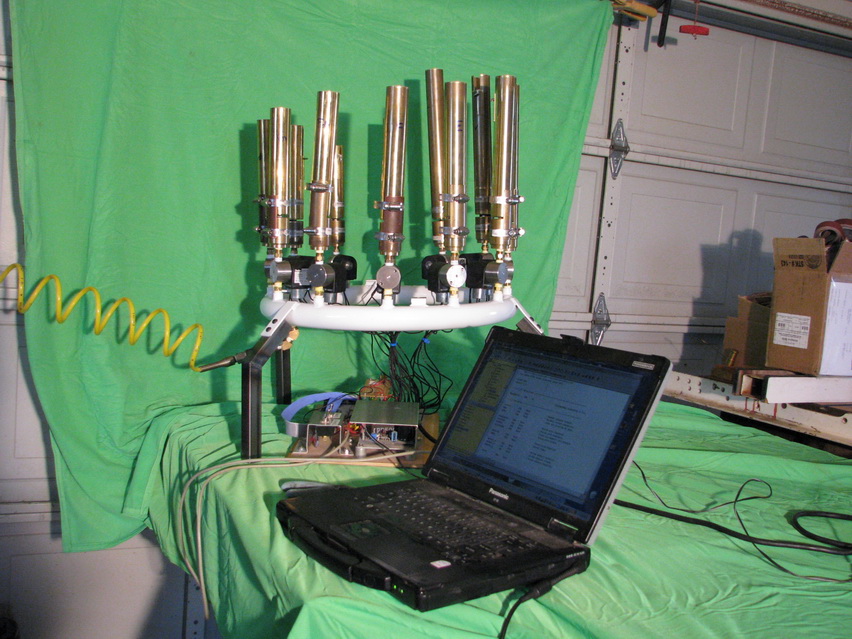
Photo #13: Trial run with prototype electronics. Note two air hoses. It was early days and valves were causing problems, not admitting enough air to run the whistles. Two hoses no better than one. 80psi needed to work properly.
|

|
|
Photo #14: March, '09: The money shot: proto electronics cleaned up a bit for Maker Fair audition video.
|
|
|
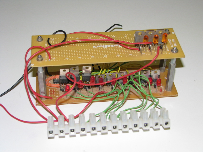
Photo #15: Shot of original breadboard; just this side of dreadful but it did work...
|
|
|
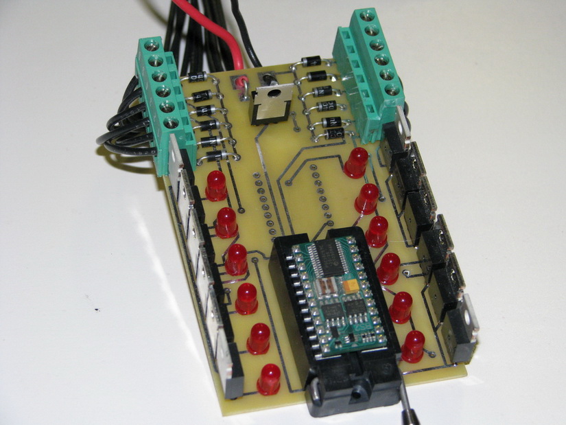
Photo #16: First iteration of circuit board, designed by Kris Magri and it totally rocks.
|
|
|
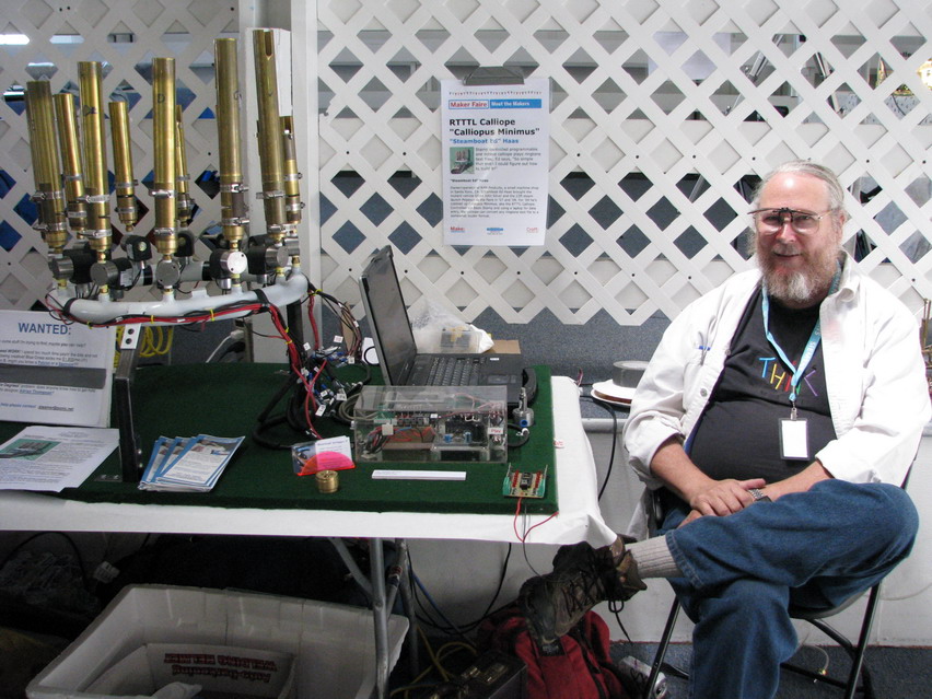
Photo #17: June, '09: Yours Truly with whole kit and kaboodle at RoboGames
|
|