Little Projects
WordPress really sucks and if anyone’s got a better interface for webbiness please let me know!! Pardon bad grammar and punctuation, but at the moment the window I’m typing into is an inch tall, permanently docked to the right of the screen and not letting me see the end of the lines I write and is generally being a pain in the ass. Last time I went to the WordPress homepage I noticed two MISSPELLINGS in their glowing descriptions of their own product; that was the capper (or is that crapper?).
Have yet to figure out how to align photos or to wrap text so this page is still a bit of a MESS.
Anywayyyy I got to a stopping point with the calliope project and decided it was time to get off my furry ass and tackle some of the little projects that have been malingering for YEARS. So in 5 days I managed to pick off three small projects; woohoo!
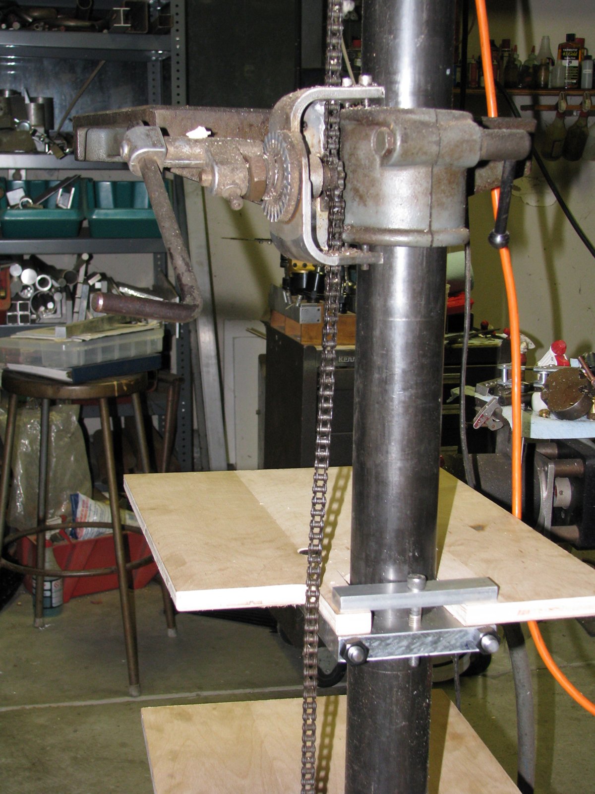
First up: for as long as I’ve had a floor-model drillpress I’ve wanted to add storage of some sort that I could hang off of the column so that all drillpress accessories, which have been gathering dust and chips on the floor, had a perch out of swarf range. Photo #1: here’s a back view of the two shelves I’ve made. The back of the plywood shelves are held down with a T-bar arrangement that uses one 3/8″ SHCS. The front and back of the clamping pieces are made of 0.8″ thick aluminum plate, held together with 1/2″ allthread and monster nuts so I’m not afraid of the thing coming apart any time soon. Note the cutout to accomodate the bicycle chain that’s part of the table raising/lowering mechanism. And no, I don’t know where to get this sort of contraption anymore; you’ll have to roll your own.
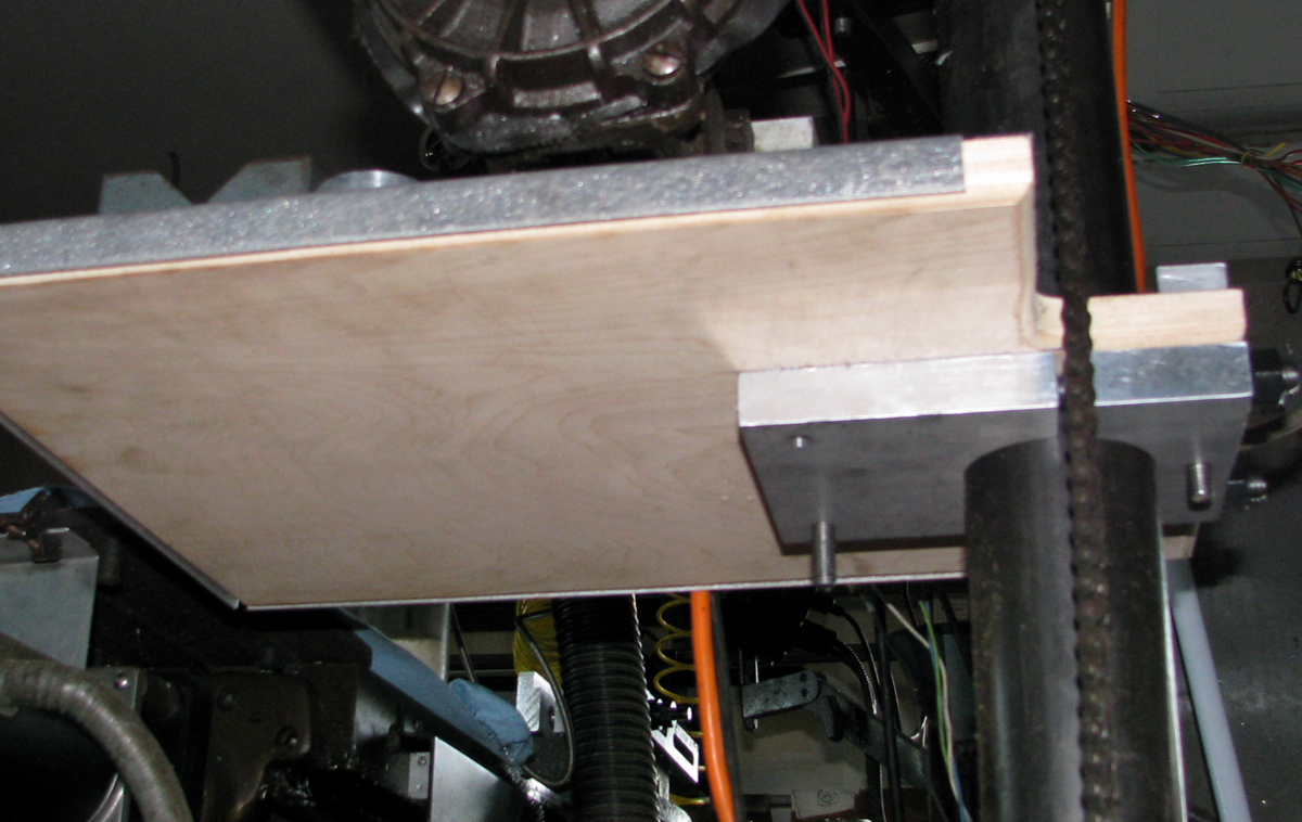
Photo #2 is a view from the underside.
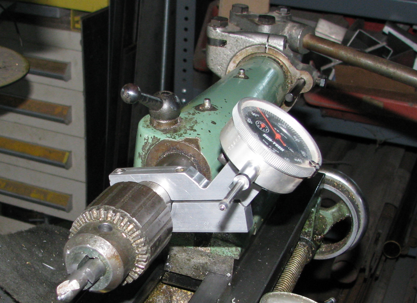
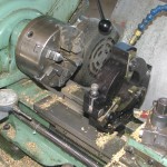
Second project was a tailstock dial indicator holder for my Myford lathe. I’d made one a few years back, but in great haste with a bandsaw. It worked adequately but was very hard to attach or adjust so it was time to do it right. Only took an afternoon. Photo #3 shows the whole thing in action; with this arrangement I can bump the gauge probe against the toolpost on the compound slide or I can flip it around, reverse the gauge and bump against something affixed to the T-slots on the compound or something attached magnetically to the chip tray. I think…
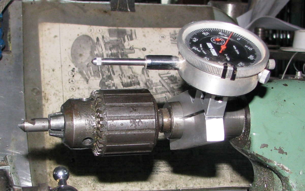
Photo #4 shows a detail from beneath; If I had bandsawed the thing right in half it would have weakened the gauge clamping point a little more than I liked, so I finished the dividing line at an angle (yes I should have stopped the long cut a little sooner!). Works great!
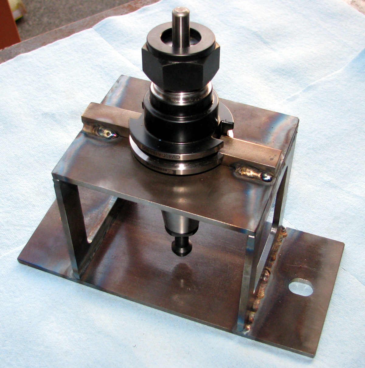
Third project: I’ve got a CNC mill that uses CAT-40 tooling. The problem is grabbing the toolholders securely while fastening cutters in the collet holders. A vise ain’t an option, as there are critical corners that could be damaged. Also one would like to be able to set tool height at least approximately, particularly if the event of tool breakage. Turns out there is a widget on the market to do this; it’s called a ‘tool presetter‘ but the one I saw cost over $400.-!! Soooo I made the one in the photo. Took 2 days due to various interruptions; big deal. Cost about $5.-. It may not be ‘precision grade’ but it’s plenty good enough for my needs.
