Art Car Progress: July, '05

Judy and I have been thru a rough patch that I don't want to talk about and it's only in the last few weeks that we've been able to stop grieving long enough to get anything accomplished.

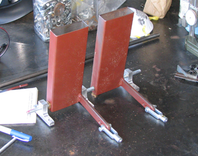
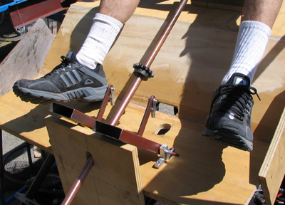
Back around July 4 Chris N. came to visit (on a 94 degree day!) and with his help and a couple of tools I banged out for the occasion we managed to reattach the modified gas and brake pedals. The trouble wasn't the attachment of the pedals so much as it was the fastening of the tension springs that cause them to return to "neutral" after each stomp. Once this was done I felt more confident fabricating the vertical link rods that will be tensioned by an upper pair of as-of-then unfabricated pedals. Friday and Saturday July 15, 16 were also terrifically productive days, thanks to the timely arrival of my campmate and pal Don Woods, who has the combined skills of a contractor and finish carpenter. With his able assistance (over two more days with temperatures in the nineties) we reached a point where I'm regaining confidence that we may, indeed, be finished in time for Burning Man.

Whilst ruminating on where the project is heading I've decided on a new name for the car. It's now called:
Short John Silver.
Heh.


Photo #1: Using a split bushing on the lathe with the 6-jaw chuck to turn a round projection onto the end of a square fitting. I made two of these bolt-on connectors, to affix aft deck supports to the vehicle's cargo rack. The existing rear suspension design decouples the vehicle's fore and aft sections with a giant pivot behind the seats. By adding these aluminum connectors to the cargo rack (that's welded to the rollcage) I can support the deck's floppy aft end without having to disable the suspension's pivot.
Photo #2: Finished connector bolted up to aft end of cargo rack. The connectors are made from 2" square stock and each is held on by four: 5/16"-18 stainless socket head bolts and a dose of Loctite.
Photo #3: First of two welded steel aft deck supports in place, fitted over the turned round end of the starboard connector. Once all has been finalized I'll cross-drill the intersections 3/16" dia. and insert hitch pins through the intersection points. The horizontal front ends of the deck supports were milled to match the contour of the aft transverse display support tube; these intersections will be welded in due course.
Photo #4: I relieved the starboard seat of its passenger-carrying duties and fabricated a new plinth from square steel tube to adapt it to the upper plywood deck, where it will become the upper driver's seat. Seat hardware included captured nuts with bolts marked 8.8mm (go figure...). This turns out to be fairly close to 5/16"-18 so retapping the nuts was easy. This assembly will be attached to the plywood with 8: 1/4"-20 bolts,using fender washers to best distribute the load beneath the plywood deck (hey, shit happens, yes?)...
Photo #5: The one bit of tackle that's fixed by the vehicle's design (and from which all other add-ons must reference) is the incredibly limited area where I could slide a sprocket onto the steering column. I've sawn a notch in the "hood" for the roller chain to pass through to the upper steering sprocket.
Photo #6: Don sits in the driver's seat so we can get a feel for where steering column and foot pedals need to be. I used a bit of 3/4" dia copper tube to simulate the steering column's precision shafting (whose length has yet to be precisely determined). Turns out although it's called 3/4" I had to sand it down quite a bit to get the upper sprocket to slide on. Once this was accomplished Don fastened the forward drilled-out bit of plywood to create a reference point. I stepped to one side and, by eye, we tilted the tube until it appeared to be parallel to the lower, original steering column-and-sprocket assembly. Don then attached the tube's top plywood support. With these I could measure vertical distances from steering column pillow blocks to the two transverse support members and start making steel sections to connect the dots.
Photo #7: With position of upper sprocket fixed directly in line with the lower sprocket Don cut a slot so the roller chain could pass freely through the upper deck.
Photo #8: While Don concentrated on cabin woodwork I set about mocking up the upper gas and brake pedal assembly. Pedals are made of square tube with pieces of 1/4 x 1/2" rectangular bar double-welded onto them. Bars have three holes apiece, so that I can adjust the sensitivity of the linkage controls. With luck this will limit top speed and provide a governor to keep some drunken fool from mashing down the accelerator; safety first and all that... Pedals are fitted on both sides with Oilite bushings to prevent binding. The three supporting pillow blocks were whittled from some 1/2" aluminum plate.
Photo #9: With steering column fixed it was time to determine upper gas and brake pedal assembly placement. Don observed that the gas pedal's welded-on "bellcrank" needs to be moved from the right, to the left side of the pedal. More grinding and welding for yours truly!
Photo #10: Thanks to Don's excellent fabrication the Cap'n's Cabin begins to take shape. Nicely done aft gallery, eh? Once painted and trimmed with EL wire it should be quite a site on the playa, day or night.

With luck Don will be paying a return visit in the next couple of weeks so we'll be able to wrap up the nasty bits. Once vehicle construction is complete I hope to lure Chris back to help me organize the wiring; he has a knack for doing it right, whereas I tend to make a mess! After that it is my profound hope that I'll have a little shake-down time before we load 'er up and fire up on the Playa!


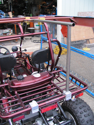
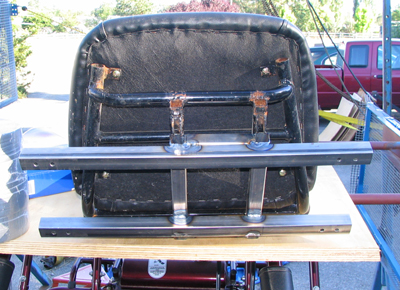
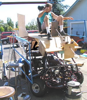
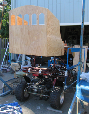
Progress as of Friday, July 22:

Photo #11: Straying into things electronic here's the bottom side of a gutted joystick game controller that I'm modifying to accept a nice, predictable linear potentiometer. Sadly it wouldn't fit into the housing so I had to connect the pot to a zero backlash coupling from the parts bin, then to a turned adapter that fastens to the joystick's original shaft. Pot will be held on the outside of the housing with a block of wood and gobs of epoxy.
Photo #12: Semi crummy PhotoShop-doctored close-up of potentiometer showing connection method. The coupling measures about half an inch in diameter at its widest. Just lucky I had one in a drawer. Although potentiometer has very limited rotation I can correct for this by tinkering with the Stamp's program. I'll wind up with a motor controller that understands variable speeds, forward and reverse and the spring-return to neutral is a real plus.

Monday, July 25: A totally wasted weekend began on Friday afternoon when I took my empty argon bottle to the Santa Rosa Praxxair dealer for a refill. Ben (the smart guy) wasn't there, so Sven (the dummy for sure...) took care of the transaction. Imagine my face when I got home, hooked up the bottle and proceeded to blow holes in my nicely jigged parts! Turns out he gave me a bottle of nitrogen by mistake. Oh, well. Put the cap back on, started to lift it back into my truck and pranged my back outta joint. Couldn't straighten up for two days!! Sunday afternoon rolls around, I take out the garbage and run into a swarm of pissed off yellowjackets who made my welding arm feel like it had recieved half a dozen flu shots. SHIT!! Finally got the bottle exchanged today and when the temperatures drop a little more and if my trots subside (what did I eat?? GACK!!) I'll start again on my "night shift".

7:50PM: I take it back; Ben's an idiot too. The new tank of Argon is empty!! Guess I'll go watch Blue Collar. Sigh.


Return to the Art Car Project
Return to  Steamboat Ed  Haas
Please send feedback to: "Steamboat Ed" Haas