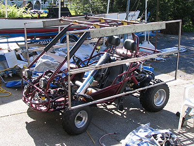
I've decided the idea of rolling hoops and stretching fabric to make a "larger" vehicle really needs a larger vehicle to be stable. Ah, well, on to Plan B. I've decided to use heavier tube for the backbones and I've started in on what's going to hang from their ends, on either side of the body. The photos below don't tell the whole story, though, as I've been doing a fair amount of bench work relating to the EL wire and the associated electronics that will be needed to control and sequence the various strands.
I'm a novice at Basic Stamp, but it's a total gas to get into this field. To date I've figured out how to use relays and I've learned the rudiments of programming them. I've yet to figure out how to trigger the various luminary routines with the touch of a button; that's on the agenda for later this month. I've also got a handle on running a big-ass motor, which will serve as a winch to raise and lower the side panels, which will have two operating regimes. While parked the panels will be folded down, but when the car is in motion they will fold along the horizontal axis and swing through an arc or 180 deg, locking on either side of the driver's position on top of the rollcage.
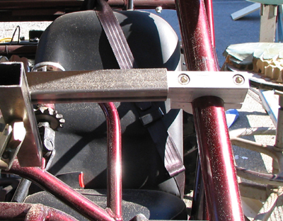
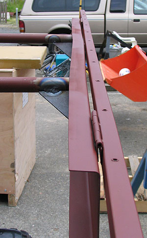
In the wee hours this morning I rediscovered the problem of building this thing with one pair of eyes: I've found a place where things will bind in the folding mechanism. It means I'll have to come up with an alternate scheme to attach the EL wire support mesh to the two upper steel frames. I've got two methods of fixing the problem. Either I can grind off the hinges, buy new material and weld it on in such a way that the hinge point is 1/8 in. farther from the edge of the frame's square tube edge, or I can go with the existing hinges, but weld nuts onto another face of the tube, so that I'll have a place to attach the #10-32 fasteners and fender washers needed to secure the mesh thru its 3/8 in. square holes. Not sure which is more of a PITA right now, so I'm working on other stuff.
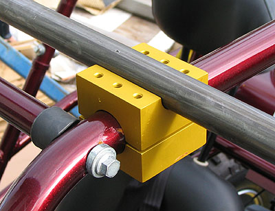
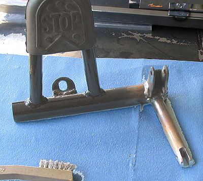
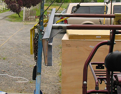
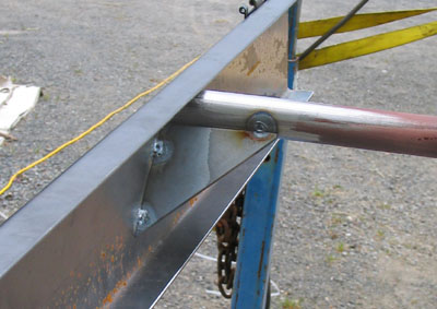
Spent the rest of the morning making gussets to secure the frame suspension channels to the ends of the backbone tubes. I got one side's gussets completely TIG weldeded and with luck I'll get started on the other side later today. Once the TIG part is done I'll have no choice but to do the final mating of the channels to the tubes with the MIG gun. I'm not great with this yet so I've been "tigging" my way around this problem whenever possible. Gotta break early for class tonight, but... Daily effort, that's the key.
Have thought about the previous problem and have come up with a half-assed solution. Went ahead, then, with the next project, which was finishing attachment of gussets to the two channels that support the mesh-covered frames. Turns out that in my zeal to get a good weld on the gussets I managed to warp the channels. This meant that the hinges, which I'd already welded onto the edges, were no longer coaxial. Once again I had two choices: whang on it with a big-ass hammer forever or brace them on something and stomp on 'em a bit. Being lazy I went for the latter option, whereupon the channel buckled. Ah, well, minimal whanging later and they're both now sufficiently lined up that the hinge pins drop in without noticeable binding. Both channels have a wrinkle in them, but these are cosmetic problems that can be dealt with later.
Once again the weather man predicted rain, so I worked towards getting channel-gusset assemblies at least tack welded to the ends of the backbone tubes. I got as far as having the port side assembly tacked and about 90% primered, leaving bare the areas where more welding needs to be done. On the Starboard side I got the channel tacked with difficulty, using TIG in a howling wind that ruined half a box of electrode points in the process. With the help of visiting Mike Butler, who's building a replacement stepper motor controller for my Bridgeport, we managed to get all and sundry under a tarp about ten minutes before the inundation began. Well, if the storm starts early, maybe it will end early, too? Lookin' forward to seeing nice art cars in San Francisco on Sunday.
Return to the Art Car Project
Return to Steamboat Ed Haas
Please send feedback to: "Steamboat Ed" Haas